Transceiver USB-UART
- theojungo
- Aug 29, 2021
- 1 min read

This second CAD (Computer Aided Design) project allows to discover and learn how to build a board with SMD components (Surface Mounted Components), as opposed to the through components discussed in the post Mixing desk.
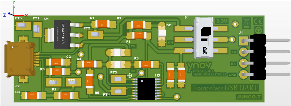
A USB-UART transceiver is an electronic device composed of a USB mini AB adapter on which is connected the computer, and a base connected to an electronic board. This transceiver allows to initialize a module before connecting it to a board.
This realization, just like that of the Mixing Board, takes place in two main stages stages:
The Conception :
The design of the circuit board is done on Altium Designer, a circuit board design software. Several steps are required to design an electronic board :
- The creation of the footprints and symbols of each component making up the board.
- The realization of the structural diagram of the board.
- The elaboration of the PCB (Print Circuit Board), in other words the board, from the structural diagram.
This whole process is explained and illustrated in the report below.
The drawing of cards :
Once the design of the card is done on the design software, simply export the work and print it on tracing paper to proceed with the printing of the card.
For the manufacture of the transceiver, in addition to the manufacturing steps for the through-hole components mentioned in the post Mixing table, new steps for the SMD components are added :
- Layout of the components on the board using solder paste.
- Reflow soldering.
This manufacturing method is detailed below.
Comentários